
Chapter 1 Preface
In order for you to better master and use the cable binding machine (commonly known as the arranging machine), please be sure to take the time to read this instruction manual carefully. If you have any questions during the reading process, please contact our sales or after-sales engineers, we will be at your service at all times.
Chapter 2 Warning
2.1 Warning
1. If the power supply of the press is connected incorrectly, it may cause malfunction or danger.
2. Do not perform wiring and installation of the press without power outage, otherwise there is a risk of electric shock.
3. Do not touch the power terminals and other live objects, otherwise there is a risk of electric shock.
4. When using the press, please do not put your hands into the press, otherwise there is a risk of injury.
5. The discharge press cannot be transported upside down.
2.2 Note
1. Please use this press within the specified operating conditions (see voltage, temperature, humidity, etc.).
2. Before starting the press, please return the moving parts of the press to the origin. Otherwise, insufficient air pressure will cause the moving parts to fall and crush the parts of the press, affecting the plane accuracy of the platform.
3. During the heating process of the press, please do not touch the heating parts and connected parts, otherwise the person who touches it will be burned.
4. Please strictly follow the process to avoid unnecessary accidents.
5. It is strictly prohibited to change the machine configuration and specifications without permission.
6. Avoid metal debris and other debris falling into the machine, otherwise a short circuit may damage the machine or cause a fire.
7. When the discharge machine fails, it is necessary to ask professionals or personnel with relevant training to repair it.
2.3 Environmental requirements
1. It should be placed away from radiation sources (such as induction cookers or microwave ovens, etc.) to avoid interference;
2. The place where it is placed must have a flat and solid ground. If unevenness is found, the caster nuts can be adjusted appropriately;
3. The place where it is placed must not be damp and must be ventilated and dry;
4. Use it in an environment with a humidity of 20% to 80% and an ambient temperature range of 0℃ to 40℃; it is not allowed to be used in an environment with a relative humidity greater than 85%, otherwise it will cause leakage and other faults;
5. The power socket must have a ground wire.
Chapter 3 Main Parameters
Model: HBD-Z14 (desktop type) HBD-Z14B (desktop type) HBD-Y14 (all-in-one)
Power supply: 220V/50Hz
Power: about 600W
Air pressure: 0.5MPa<Air pressure<1MPa Compressed air must be dry, moisture-free and impurity-free, otherwise the air circuit will be easily damaged.
Net weight: desktop type about 55Kg, all-in-one type about 88Kg
Chapter 4 Introduction to the whole machine


Chapter 5 Material Preparation
1. Gas and electricity preparation: one air compressor with a capacity of 40L or above, 220V/50Hz lighting electricity.
2. Preparation of tools for pressing and discharging materials:

Chapter 6 Ventilation and Electricity
1. will¤ 8 Insert the air pipe into the quick connector of the air filter, pull up the adjustment knob, and limit the air supply pressure to about 0.6MPa (as shown on the left below).Open the cabinet and adjust the air supply pressure of the meter to 0.2MPa (as shown on the right below).
2. Plug the power cord into the socket of the machine, turn on the power switch, the machine display and display and control screen should light up, and the pressure head should return to the highest point.(As shown in the middle picture below)


Chapter 7 Explicit Control Learning
(1). Turn on the power switch, and the display will appear after self-test.“Main interface”, generally click“Enter the system”。
(2). After entering the system, you will enter by default“Manual operation”Interface:
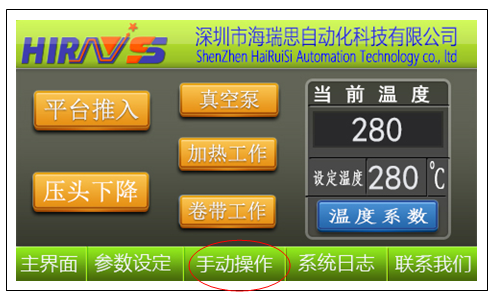
Manual operation function description:
1. Platform push: After clicking, the workbench component that turns blue will be pushed in, and by clicking again, the workbench component will be pushed out;
2. Pressure head decreases: After clicking, the pressure head component will turn blue and it will drop. Click again and the pressure head component will rise;
3. Vacuum pump: Click it to turn blue and the vacuum pump will work. Click it again to stop the vacuum pump.In production status, press the vacuum switch on the machine panel, and the vacuum pump will work automatically;
4. Heating work: After clicking, the pressure head turns blue and starts heating, and stops heating when it reaches the set temperature.Click again to stop heating;
5. Tape winding work: After clicking, it turns blue, and the tape winding motor rotates clockwise according to the set tape winding time (see the tape winding time).“Parameter setting” column, the parameters need to be set in advance, otherwise the motor will not rotate). After the rotation time is reached, the winding motor will automatically stop;
6. Current temperature: Displays the currently set temperature value or ambient temperature value;
7. Set temperature: Click and directly enter the temperature value you want to set;
8. Temperature coefficient: It is used for internal setting in the factory. Once it has been set before leaving the factory, there is no need to change it.
(3). Click parameter setting to enter“Parameter setting”Interface:
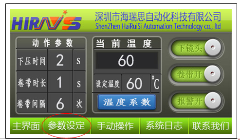
Parameter setting function description:
1. Pressing time: that is, the length of time the pressure head is held after pressing down. You can directly enter the number after clicking. The debugging of the pressure head is generally 2 seconds, and the pressure discharge is generally 14+/-2 seconds;
2. Tape winding time: This is the length of time the tape winding motor works. You can directly enter the number after clicking it. It is generally set to 1 second.The setup time is too long, resulting in waste of tape;
3. Taping interval: that is, how many times the press is pressed and the tape is wound once. It is generally set to 6 times, that is, the press head works 6 times and the tape is wound once (the used part is rolled away).
4. Lower lens: After clicking, the lower lens changes to the upper lens, and the upper lens camera works (the default is the lower lens when it is turned on);
5. Tape on: Click to turn it into tape off. Instead of turning off the tape motor, it turns off the tape interval under working conditions. In this way, no matter how many times it is pressed, the tape motor will not automatically rotate once (for debugging);
6. Alarm on: Click to change to alarm off. Currently, the alarm sound function is not used.
(4). Click the system log to enter“System log”Interface:

System log function description:
1. Output Clearance: Click to clear the current output accumulation;
2. Clear when tired: Click to clear the current work accumulation;
3. Alarm information: displays the current alarm record.
Chapter 8 Indenter debugging (flatness debugging)
Before each pressure discharge or after each replacement of the pressure head, the flatness of the pressure head must be debugged. The flatness debugging of the pressure head must be performed at room temperature. The steps are as follows:
1. Click“Manual operation”will“Set temperature”Set to 60 degrees and wait until the temperature rises to the set temperature;
2. Click“Parameter setting”, will“Press down time”Set to 2 seconds;
3. Adjust the pressure of the pressure regulating valve to about 60-150KGF;
4. Click“Manual operation”, click“Platform push”;
5. Fold a piece of white paper in half, sandwich a piece of carbon paper in the middle of the folded white paper, and put the white paper under the knife head;
6. Click“The pressure head decreases”, press the indenter on the white paper, and the indentation will appear as shown below:
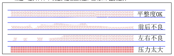
7. If the test pressure is too high, reduce the test pressure appropriately;
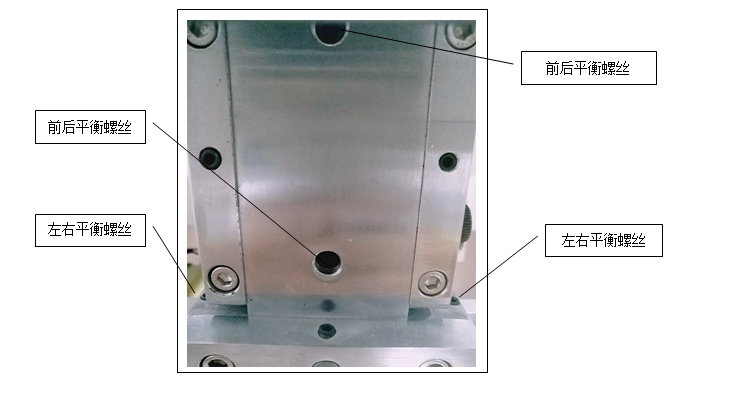
8. If there is poor left and right flatness, you can adjust the left and right balance screws;
9. If there is poor front and rear flatness, you can adjust the front and rear balance screws;
Note: After each adjustment, test it again until the flatness is OK.After debugging is completed, turn off the heating.The above parameter settings: 1. Temperature 60 degrees, 2. Pressure 60-150KGF, 3. Pressing time 2 seconds.
Notice:
1. Generally, there is no need to adjust the front and rear flatness. If it needs to be adjusted, it is only fine-tuning.
2. The fastening screws must be tightened, otherwise the flatness will easily change.
Take Apple 5S as an example to illustrate the entire pressing process:
Chapter 9 Disassemble the wiring
***Tools used: Constant temperature heating table and toothpicks
1.1 Adjust the temperature of the heating table to 300 degrees and wait for the temperature to reach;
1.2 Place the LCD screen on the constant temperature heating table (note: the cable side is facing up) for a few seconds;
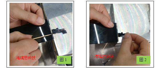
1.3 Remove the touch cable: Use a toothpick to insert from the middle of the touch cable, select the left (or right) touch cable, and slide it over where the cable is connected to the LCD (as shown in Figure 1). The cable and LCD will be separated; the other side can be gently torn off directly.(Note: If it is confirmed that it is a cable problem, such as broken, the left and right touch cables can be torn off directly);
1.4 Remove the display cable: gently tear it off after heating (as shown in Figure 2).
Notes on the above: During the process of removing the cables, be careful not to damage the edges and corners of the LCD screen.
Chapter 10 Removing adhesive residue from LCD screen
***Tools used: ACF removal fluid, white electric oil and cotton swabs (it is recommended to use an electronic magnifying glass and glue removal platform, which is more efficient and convenient)
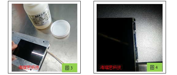
2.1 Dip a cotton swab into the ACF removal solution, then apply it on the LCD screen and wait for a while.
2.2 Use a cotton swab to gently smear the residual glue on the LCD. During the application, you can also dip it in some white electric oil until it is completely removed (Figure 3).
2.3 Use the light to check whether the residual glue is completely removed (Figure 4).(This affects the success rate of pressure removal. It is recommended to use an electronic magnifying glass)
Notes on the above:
1. Human skin should not come into contact with the ACF removal solution. If it does come into contact accidentally, wash it with plenty of water;
2. The ACF removal liquid cannot flow back into the liquid crystal IC (usually tilting is used);
3. You can use the ACF glue removal platform to remove residual glue, which will be more efficient and safer;:
4. Inspection after the residual glue is removed can be done with the naked eye, or with the help of a magnifying glass or the two-in-one magnifying glue removal platform of Hai Ruisi;
5. When removing glue, be careful not to break the edges and corners of the LCD glass. The glass must be kept flat when removing glue.:
Chapter 11 Applying ACF glue to the cable
***Tools used: ACF glue and constant temperature soldering iron
3.1 Take the touch and display cables of the corresponding model;
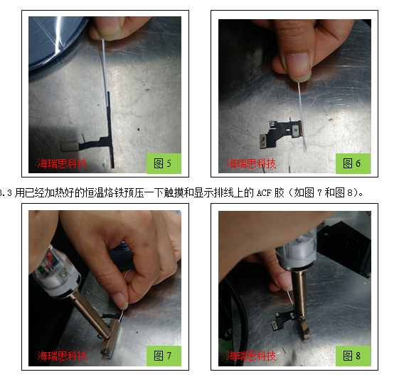
3.2 Just like applying double-sided tape, put ACF glue on the touch and display cables respectively (Figure 5 and Figure 6)
Notes on the above:
1. ACF glue should be attached to the middle of the gold finger of the cable, and a certain length should be reserved at both ends;
2. The pre-pressure time of the constant temperature soldering iron is about 3 seconds.
Chapter 12 LCD screen height calibration
LCD screen height calibration is to balance the heights of the LCD screen, workbench, and quartz strip. The method is as follows:
1. Place the LCD screen on the workbench, with the cable end facing the quartz strip;
2. Move the LCD screen back and forth toward the quartz bar, and use the Z-axis lifting screw of the fine-tuning workbench to ensure that the cable end of the LCD screen does not hit the quartz bar and that the LCD screen can be placed on the quartz bar when moving back and forth. At this time, the height of the quartz bar should be slightly higher than the height of the workbench.(See the picture below) After adjustment, tighten the height Z-axis locking screw.
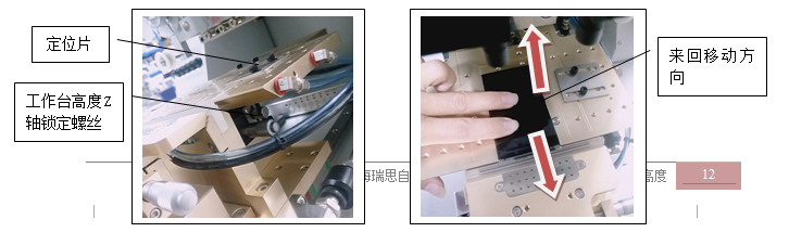
Note: The height calibration of the LCD screen is an important step in pressing the screen. If it is not calibrated properly, the LCD screen will be crushed when pressing the screen.
Chapter 13 LCD screen positioning
LCD screen positioning is to align the pressing position of the pressure head with the center of the LCD screen installation cable, and then use positioning pieces on the workbench to fix the placement of the LCD screen.The specific steps are as follows:
1. Adjust the pressure of the pressure regulating valve to 60-150KGF;
2. Click Display Control“Manual operation”, click“Platform push”To make the work platform push, click“The pressure head decreases”Lower the pressure head.
2. Reduce the pressure of the pressure regulating valve slightly, and then lift the pressure head with one hand;
3. Place the LCD screen under the pressure head with the other hand, and place the cable arrangement in the middle of the quartz strip;
4. Gently lower the pressure head and press it on the LCD screen;
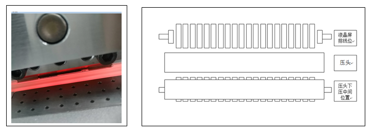
5. Fine-tune the position of the LCD screen from front to back, left and right, so that the pressure head is just in the middle of the LCD screen mounting cable (as shown below);
6. Click Display Control“Vacuum pump”Hold the LCD screen, and move the positioning piece on the workbench close to the edge of the LCD screen to set the positioning point.Click“The pressure head decreases”Raise the pressure head and click“Platform push”Exit the work platform;
7. Take away the LCD screen, put the LCD screen again, and click“Platform push”To make the work platform push, click“The pressure head decreases” Lower the pressure head and observe whether the center of the pressure head is pressed in the middle of the LCD screen mounting line. If not, fine-tune it appropriately.
8. Confirm that there is no problem with the positioning, click“The pressure head decreases”Raise the pressure head and click“Platform push”Exit the working platform; Note: Adjust the distance between the indenter and IC (if there is an IC), and reserve the position of buffer material between the indenter and IC, otherwise defective products will be pressed out or the IC will be crushed.
Chapter 14 Pressing and arranging cables
Pressing the cable is divided into pressing the display cable and the touch cable. The methods and steps are as follows:
(1) Press the display cable
***Tools used: press and masking tape
Note: The display cable is under the touch cable, so you need to press the display cable first and then the touch cable. This is exactly the opposite order of removing the two cables.
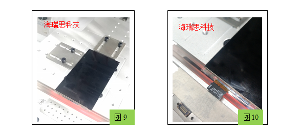
4.1 Place the LCD screen with residual glue removed in front of it into the positioning piece limit of the glass working platform of the press (as shown in Figure 9);
4.2 Click“Manual operation”will“Set temperature”Set to 260-290 degrees;
4.3 Adjust the pressure of the pressure regulating valve to 260-300KGF;
4.4 Click“Parameter setting”will“Press down time”Changed to 15 seconds,“Tape length”Set to 1 second,“Tape interval”Set to 6 times;
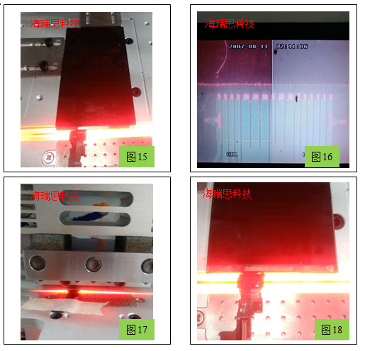
4.5 Tear off the ACF glue protective layer on the display cable, then roughly cover it on the LCD display cable, and use a vacuum to suck the other end (you need to click on the display control“Vacuum pump”) or fix it with masking tape (as shown in Figure 10);
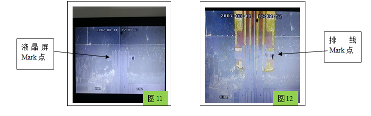
4.6 clicks“Parameter setting”Switch the compressor to the lower lens (the lower lens is the default when starting up), adjust the coaxial light potentiometer and quartz light potentiometer of the lower lens, and adjust the XYZ axis of the camera to make the displayed image the clearest; (Figure 11)
4.7 Adjust the XYZR four-axis micrometer on the cable arrangement workbench so that the origin of the cable arrangement coincides with the origin of the LCD screen cable arrangement (Figure 12);
4.8 Press the vacuum button and machine start button, the workbench will be automatically pushed in, the pressure head will be pressed down, and the pressure will be maintained at constant temperature (Figure 13);
4.9 After 15 seconds, it is completed, the pressure head automatically rises, the workbench exits, and the cable arrangement is completed (Figure 14).Notes on the above:
1. During operation, be careful not to touch high temperature parts.
2. The alignment of the cables must be accurate. If the cables are pressed out of the way, they may be short-circuited, resulting in abnormal or no display.
3. If the pressure is not tight, please increase the pressure or increase the temperature appropriately.
(2) Press the touch cable
***Tools used: press and masking tape
Note: The difference between the touch cable and the display cable is that it is distributed on both sides of the LCD. When pressing, the touch cable cannot be pressed into the middle of the display cable.
Method 1: The steps for pressing the display cable are the same as before, except that when aligning, you need to adjust the left and right lenses to confirm. You can press one side first, and then press the other side;
Method 2: The steps for pressing and arranging the display cable are the same as before, but you can use a special cutter head to press it once instead of twice.
Chapter 15 Checking the Pressure Discharge
After the pressing and arranging is completed, first conduct a visual inspection to see if there is any misalignment or deviation; then do a tensile inspection, that is, pull the arranging cable with a little force to see if it will fall off; then insert it into the test stand for testing. If it can display and touch normally, it is considered OK (Figure 19).
Chapter 16 Pressure Supplement
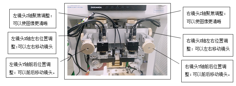
(1) Regarding the use of the camera
use
When the LCD screen is not transparent glass, you need to use the upper lens to work, such as Samsung S6S7, the method is the same as the lower lens.
(2) Operation sequence of pressing and discharging:
Put in the LCD screen -- press the vacuum switch -- put the cable in place -- align the cable with the LCD screen -- press start– The workbench is pushed in - the pressure head is pressed down - the pressure is maintained - the pressure head is raised - the pressed screen is taken out - the LCD screen is put in. Repeat the above and work in a cycle.
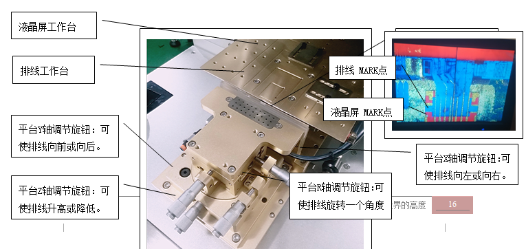
(3) Introduction to the cable arrangement workbench
Place the cable on the cable arrangement workbench. The cable must be within the vacuum adsorption range (or fixed with masking tape). Observe the coincidence of the MARK point of the cable and the glass cable with the MARK point of the LCD screen. Adjust the X, Y, and R axes to move the Mark point until it coincides with the Mark point of the glass.
Chapter 17 Maintenance
After the equipment has been running for a period of time, the following inspections or parts replacement are required.
1. Press head: It needs to be cleaned regularly, and it must be ensured that there are no foreign objects on the press head.
2. Thermocouple wire: The temperature needs to be checked regularly. If a large temperature deviation is found, the thermocouple needs to be replaced.
3. The screw tightening status of each mechanism needs to be checked regularly. If the screws are found to be loose, they need to be tightened in time, once a week.
4. Regularly clean up the dust and debris that fell into the machine, and cut off the power and air source before cleaning.
5. All moving parts must clean the solidified lubricating oil and add new lubricating oil (once a month).
6. The flatness of the cutter head should be checked once a day to ensure production quality and the service life of the indenter.
7. Drain water from the filter regularly, and cut off the power and air source before draining.
Chapter 18 Common faults

-
2026.04.11Good News | Hirays Honored as "Most Investment-Worthy Enterprise" at 2026 AI Glasses China Tour
-
2026.04.11Why are more and more companies opting for RGA technology for power bank electrolyte leakage detection?
-
2026.03.30Commemorating the revolutionary martyrs and inheriting the red spirit | Record of hirays’s theme activity of walking to commemorate the martyrs’ cemetery
-
2026.03.20Starting from June, the sale of non-compliant power banks will be banned: many companies ignore this detection issue
-
2026.03.16After charging 70% in 5 minutes, how can the safety of the power battery be maintained?
-
2026.03.14Overcoming difficulties and showing responsibility, efficient delivery wins praise - a tribute to the four pioneer employees on the production front line
-
2026.03.03Comparison of mass spectrometry technology applications: How do Heris helium mass spectrometers and RGA series enable precision manufacturing?
-
2026.02.26Construction has started | hirays starts a new journey of struggle in 2026
-
2026.02.06Let’s work together to embark on a new journey | The 3rd hirays Fun Games was successfully held
